BatchDrake
Hacking, HAM Radio (EA1IYR), DSP, physics and more

Hacking, HAM Radio (EA1IYR), DSP, physics and more
We refer with the generic name of “quadrature demodulators” to those demodulators that take a complex I/Q signal as input. Although this is a critical step of the demodulation process, it may also be the simplest to implement.
Let’s start by giving a look to the mathematical expression that summarizes the transmitted signal of an ideal FM modulator. If \(x(t)\) is the baseband signal, the transmitted signal \(y(t)\) will look like this:
\[y(t)=\text{cos}\left[2\pi f_ct+\pi\Delta f\int_0^tx(\tau)d\tau\right]\]With \(f_c\) being the carrier frequency. Assuming that the baseband signal’s range is \([-1, 1]\), \(\Delta f\) corresponds to the maximum bandwidth of the transmitted signal. It is clear that if \(x(t)\) is constant then \(y(t)\) is just a cosine of fixed frequency. If not, the instantaneous value of \(x(t)\) is treated as the amount of radians per unit of time (i.e. frequency) that should be added or subtracted from the carrier phase. If \(x(t)\) becomes negative, the resulting cosine has an instantaneous frequency lesser than \(f_c\). If positive, the resulting instantaneous frequency is greater than \(f_c\).
If we want to recover \(x(t)\) from \(y(t)\), then we need to undo two things: the cosine and the integral.
In the previous post, we created a numerically controled oscillator to perform a frequency shift on the received signal and center it around DC. Because its spectrum is not symmetric, we can be say that the resulting signal is complex.
The signal we centered earlier is not the cosine we showed above, but its positive component. A cosine of frequency \(f_c\) has two spectral components: one at \(+f_c\) and another at \(-f_c\). This is not surprising, as the cosine can be written as:
\[\text{cos}(x)=\frac{e^{jx} + e^{-jx}}{2}\]In extremely simplified terms, when the SDR device performs quadrature demodulation on the RF signal, it shifts both components by the same amount, falling one (let’s say, the positive one) near DC while the other one gets filtered out. If the tuner frequency is \(f_t\), the complex signal that feeds the ADC is roughly like:
\[x(t)=Ae^{j\left[2\pi (f_c-f_t)t+\pi\Delta f\int_0^tx(\tau)d\tau\right]}\]With \(A\) some arbitrary constant phasor. This means that what we have to undo here is not the cosine, but the complex exponential.
In this approach, we first undo the exponential and then derive the exponent. As differentiation is the inverse operation of integration, by calculating the derivative of \(\pi\Delta f\int_0^tx(\tau)d\tau\), we get something proportional to \(x(t)\).
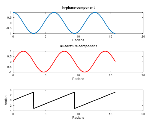
Since the exponent is purely imaginary, we can retrieve it by computing the argument of the complex exponential. This is, atan2(Q, I) (or carg(x), if we work with complex numbers directly). Unfortunately, this will not work as we expect: even though we can technically recover the phase of a complex exponential through the arctangent, the value returned by this function will be in the range \([-\pi,\pi]\) rad, with a \(2\pi k\) rad ambiguity. This implies hard (\(2\pi\)) discontinuities when the phase approaches \(\pi+2\pi k\) that will eventually affect the derivative:

The problem with the previous approach is that it is not easy to unambiguosly retrieve the phase to perform the derivative. We know that the phase grows smoothly, but this is not reflected in the arctangent.
In this approach, we will think in reverse. We attempt to perform the derivative before retrieving the phase. And how is this even possible? First, let’s think about the following approximation of the received and discretized signal:
\[x[n]=A[n]e^{j\left[2\pi \frac{f_c-f_t}{f_s}n+\pi\frac{\Delta f}{f_s}\sum_{\nu=0}^nx[\nu]\right]}\]Where \(A[n]\) is some phasor that assimilates both the amplitude and phase noise of the received signal.
The multiplication of two exponentials equals to the exponential of the sum of the exponents. Conversely, the division of two exponentials equals to the exponential of the difference of the exponents. We can exploit this property to estimate the exponential of the derivative of the exponent:
\[\frac{x[n]}{x[n-1]}=\frac{A[n]}{A[n-1]}e^{j\left[2\pi \frac{f_c-f_t}{f_s}n+\pi\frac{\Delta f}{f_s}\sum_{\nu=0}^{n}x[\nu]\right]-j\left[2\pi \frac{f_c-f_t}{f_s}(n-1)+\pi\frac{\Delta f}{f_s}\sum_{\nu=0}^{n-1}x[\nu]\right]}\]By simplifying the exponent:
\[2\pi \frac{f_c-f_t}{f_s}n+\pi\frac{\Delta f}{f_s}\sum_{\nu=0}^{n}x[\nu]-2\pi \frac{f_c-f_t}{f_s}(n-1)-\pi\frac{\Delta f}{f_s}\sum_{\nu=0}^{n-1}x[\nu]=2\pi\frac{f_c-f_t}{f_s}+\pi\frac{\Delta f}{f_s}x[n]\]And therefore: \(\frac{x[n]}{x[n-1]}=\frac{A[n]}{A[n-1]}e^{j\left[2\pi\frac{f_c-f_t}{f_s}+\pi\frac{\Delta f}{f_s}x[n]\right]}\)
Which is a discrete signal whose phase is proportional to \(x[n]\) plus some bias term related to the offset between the carrier frequency and the local oscillator. As long as the sampling frequency is big enough to capture the variation of \(x[n]\) without aliasing, we would be able to recover the original signal by applying the arctangent to the I/Q components as usual.
This approach, although flawless in first sight, has some numerical stability issues. If \(x[n-1]\) randomly becomes zero because of the noise, the division may result in a NaN that propagates through the arctan, spreading along the AGC buffer like a virus and eventually corrupting the demodulator output.
Fortunately, for purely imaginary exponents, there is another way to invert their sign without dividing. We just need to take its complex conjugate, which is equivalent to inverting the sign of its imaginary part. Indeed:
\[e^{jx}=\text{cos}(x)+j\text{sin}(x)\\ \bar{e^{jx}}=\text{cos}(x)-j\text{sin}(x)\]And since the cosine is a symmetric function, while the sine is an antisymmetric function:
\[\bar{e^{jx}}=\text{cos}(x)-j\text{sin}(x)=\text{cos}(x)+j\text{sin}(-x)=\text{cos}(-x)+j\text{sin}(-x)=e^{-jx}\]Therefore, if we multiply the current sample by the complex conjugate of the previous sample:
\[x[n]\bar{x}[n-1]=A[n]\bar{A}[n-1]e^{j\left[2\pi \frac{f_c-f_t}{f_s}n+\pi\frac{\Delta f}{f_s}\sum_{\nu=0}^{n}x[\nu]\right]-j\left[2\pi \frac{f_c-f_t}{f_s}(n-1)+\pi\frac{\Delta f}{f_s}\sum_{\nu=0}^{n-1}x[\nu]\right]}\]And after simplifying the exponent:
\[x[n]\bar{x}[n-1]=A[n]\bar{A}[n-1]e^{j\left[2\pi\frac{f_c-f_t}{f_s}+\pi\frac{\Delta f}{f_s}x[n]\right]}\]Note that:
\[\text{arg}(x[n]\bar{x}[n-1])=2\pi\frac{f_c-f_t}{f_s}+\pi\frac{\Delta f}{f_s}x[n]+\text{arg}(A[n]\bar{A}[n-1]) = M x[n]+N[n]+B\]Which is proportional to the transmitted signal plus some constant DC component \(B\) and a (hopefully small) noise term \(N[n]\).
What a long explanation for something so simple! In fact, the only changes we need to introduce in our code are:
This takes no more than two lines in total. The new complex variable will be called previous, and the modified loop will now look like this:
  prev = 0;
  while (fread(&x, sizeof(SUCOMPLEX), 1, fp) == 1) {
    x *= su_ncqo_read(&nco1);      /* Center spectrum */
    x = su_iir_filt_feed(&lpf, x); /* Filter centered signal */
    x *= su_ncqo_read(&nco2);      /* Center signal around the black level peak */
    y = carg(x * conj(prev));      /* Perform FM detection */
    prev = x;                      /* Save previous sample */
    fwrite(&y, sizeof(SUCOMPLEX), 1, ofp);
    ++samples;
  }
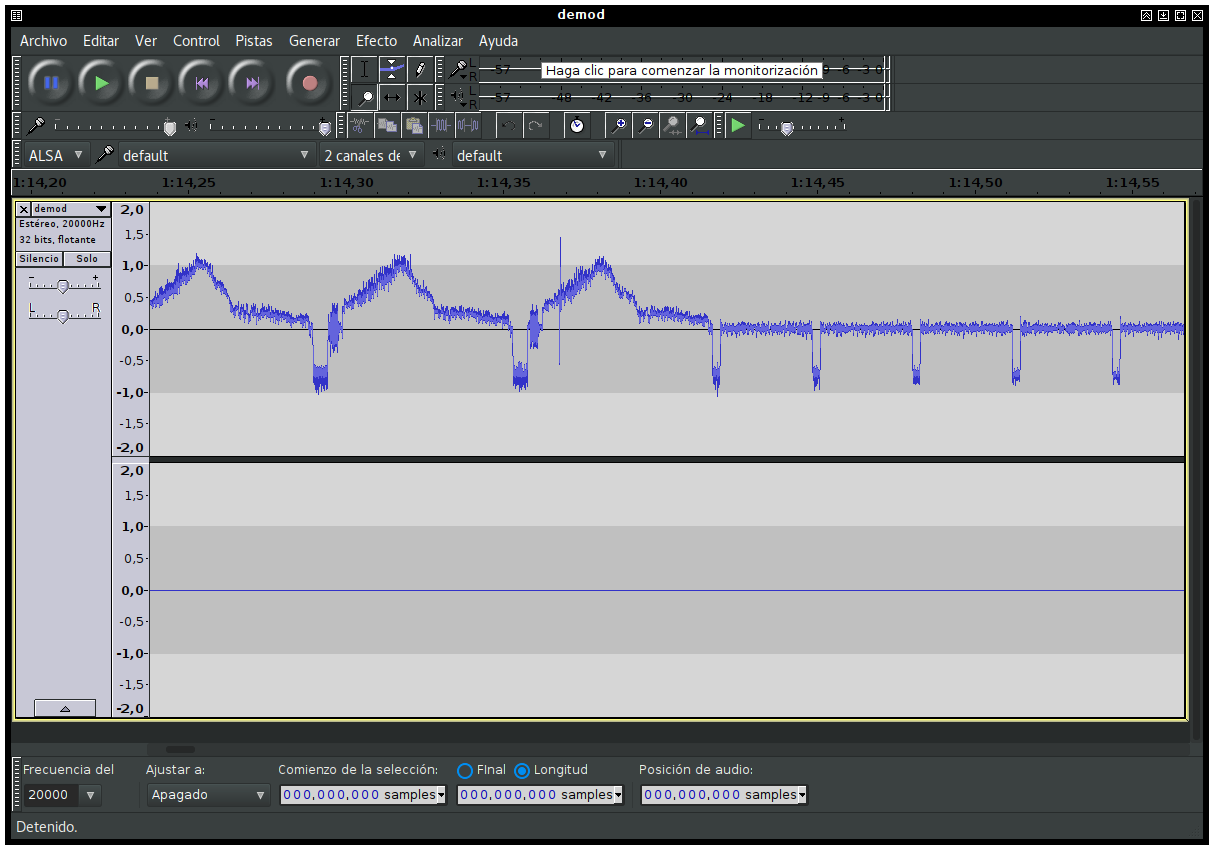
If we open the output file with audacious (raw file, 20ksps, 32 bit float stereo), we should see something like this:

Since carg returns a single-precision float number and y is still a complex variable, the imaginary part of it will now be zero. This is reflected in audacity, which shows the second channel as perfectly silent.
The first channel, on the contrary, shows the result of our detection. These repeating patterns are in fact individual NTSC scan lines:

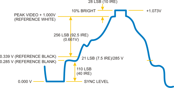
Since we manually centered the FM spectrum around the black level peak, we can see that sync pulses are negative while black is somewhere around zero. This is exactly the output we expected :)
The received signal has been frequency-demodulated, and now we have a baseband NTSC video signal. We could be tempted to transform these levels into a stream of pixels directly and paint them on a screen. However, there is something we didn’t arrange yet: the amplitude of the signal. If we cannot control the minimum and maximum levels of the resulting signal, we cannot know how much brightness each level corresponds to.
Although all of this boils down to knowing the sample rate \(f_s\), the channel bandwidth \(\Delta f\) and the DC offset, we will assume that at least one of these parameters is not known, forcing us to try to guess the signal limits in real time.
In our next post, we will learn a bit about software AGCs and how they can help us stabilize the amplitude of the FM detector output. Stay tuned!