
BatchDrake
Hacking, HAM Radio (EA1IYR), DSP, physics and more
Hacking, HAM Radio (EA1IYR), DSP, physics and more
As every year since my first experiments with GRAVES (at some point around 2018), I got ready to listen to some falling stones during the Perseids meteor shower. Nonetheless, I wanted to give it an interesting turn this year: instead of listening to the echoes and measuring the mesospheric winds (whose interest is limited), how about doing some direction finding on the received echoes?
This, of course, it is easier said than done. Once again, I was limited by my resources, although not as much as past years. They toy box consisted of the following items: two phased half wavelength dipoles), a couple of VHF bandpass filters, an AntSDR e310 with 2r2t mode enabled and an ugly hack for SigDigger.
In this post I will cover a few of the topics I like the most: space, radio, interferometry (kind of) and programming.
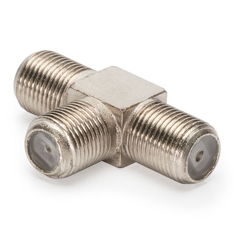
I departed from a reinforced version of the antenna I used while I was studying my master’s on Astrophysics back at UCM. This earlier version consisted of two half-wave dipoles, with a half-wave separation and a regular RG-6 coax (75 ohm) connected to both. The cables were connected to an F-connector tee, and from there to an AirSpy Mini.
By cutting the cables with different lengths, I could adjust the relative phase with which the signals coming from both antennas would combine. This provided me with some (rudimentary) tunable directivity that, once set, would optimize the phased dipoles to a preferred direction.
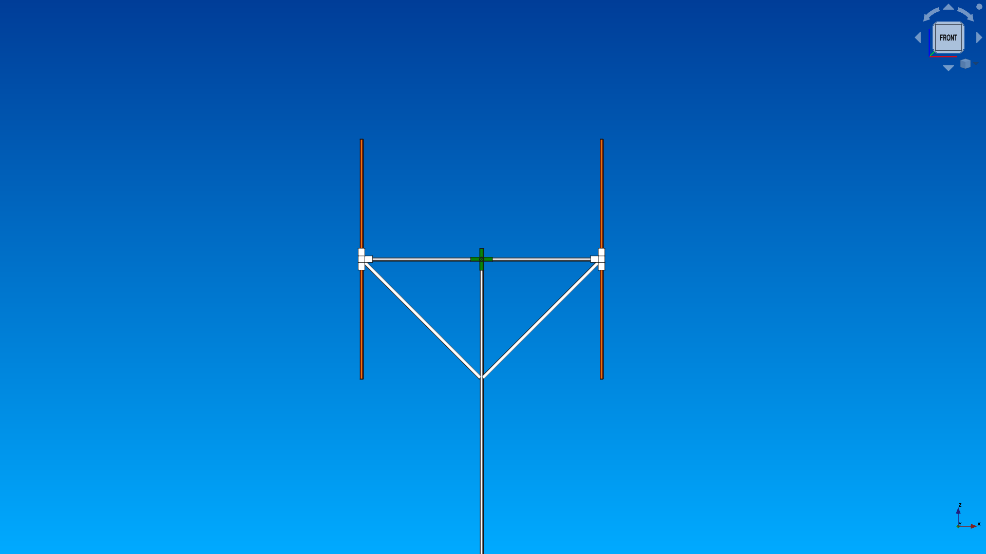
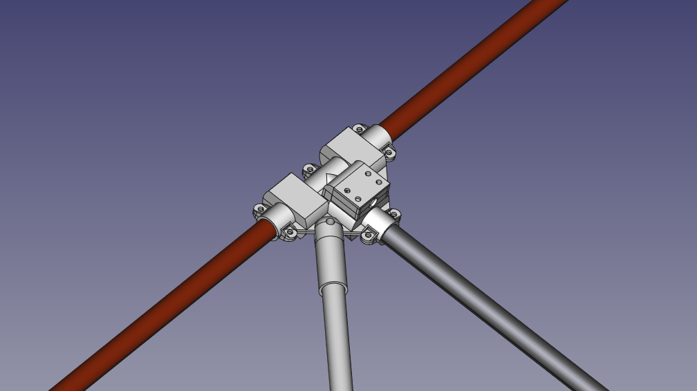
The reinforced version of the antenna relied on custom 3D-printed parts for the enclosures, the dipole support joints and the coax-dipole connection. It also featured a couple of diagonal plastic struts to reduce the quivering of the horizontal support holding both dipoles. Acrylonitrile styrene acrylate (ASA) was the ideal material for this project due to its excellent properties in outdoor conditions. In fact, the dipole array stayed in a corner of my terrace for more than a year, exposed to rain, Sun, snow, insects and dirt before I actually used it, and it did its job quite well.
Additionally, as I needed to compare the phases of both antennas at software level, I happily removed the tee and cutted both cables to approximately the same size. Two F connectors were crimped to them, and from there to 2 F-to-SMA adapters. The mismatch loss due to the 50-75 transition is barely 0.2 dB, which is more than acceptable for our purposes.
Now I have those two dipoles with two coax cables coming from them. My plan is to connect those cables to a coherent receiver, and perform phase comparisons between the same signal in both antennas to determine the angle of arrival. But, what is the relationship between phase difference and angle of arrival?
We start by simplifying our problem a bit. First of all, our dipoles are vertical. This is imposed by the properties of the GRAVES radar: the radar signal is vertically polarized, and therefore our antennas should be vertically oriented as well. Dipoles are very sensitive to radio waves propagating perpendicularly to their axis, and very insensitive to radio waves propagatin along their axis. This means that our array will be sensitive to the horizontal components of the received echoes.
Additionally, since our array consists of just two dipoles, we are going to have certain angular ambiguity. Indeed, with this setup we can measure the angle the wavefronts make with respect to the array’s normal vector (i.e. the vector perpendicular to the plane containing the array), but not from which side of the plane they are arriving. In practice, this means that we cannot distinguish a signal with an angle of arrival α from a signal with an angle of arrival \(180º - \alpha\).
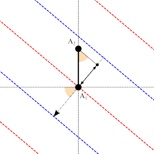
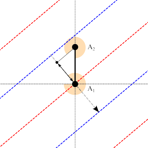
Finally, the Doppler effect of the ionization trails will introduce a slight frequency shift of a few tens of Hz, and hence the relationship between phase difference and angle of arrival. Since this shift is much smaller than the channel frequency (more than 1000 times smaller), we can further assume that the wavelength of the echoes is roughly the same, and the impact in the angle measurements negligible. With all these considerations in mind, we can sketch a diagram of our antenna array, as seen from above:
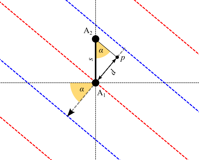
From this diagram it follows that, when the echoes arrive with an angle α = 0º with respect to the plane normal (horizontal axis in the previous picture), the wavefronts will hit both dipoles at the same time, and their phase difference will be 0º. On the other hand, if \(\alpha\) is non-zero, the same wavefront will arrive to each dipole at different times, resulting in a phase difference between \(A_1\) and \(A_2\) (in radians) of:
\[\Delta\phi=2\pi f_0\Delta t\]With \(f_0\) the frequency of the wavefronts (close to 143.050 MHz). At the same time, the time lag \(\Delta t\) observed between dipoles is related to the delay length \(d\) by:
\[\Delta t = \frac{d}{c}\]With \(c\) the propagation speed of the wavefronts (i.e. the speed of light). This delay length is obtained from the angle of arrival \(\alpha\) as:
\[d=s\text{ sin }\alpha\]The full equation relating the phase difference and the angle of arrival is therefore:
\[\Delta\phi=2\pi f_0\frac{s\text{ sin }\alpha}{c}=2\pi\frac{s}{\lambda}\text{sin }\alpha\]In our particular setup, dipole separation equals half of the wavelength, and our equation becomes even simpler:
\[\Delta\phi=\pi\text{ sin }\alpha\]Therefore, from our measurement of the phase difference, we can obtain (one) possible angle of arrival as:
\[\alpha=\text{arcsin}\left(\frac{\Delta\phi}{\pi}\right)\]With \(\alpha\) is in radians. The other possible angle of arrival is simply \(\pi - \alpha\), due to the angular ambiguity of the array.
The most critical part of this experiment is the receiver. For this purpose, I acquired an AntSDR e310 some time ago. The AntSDR is basically an improved realization of the PlutoSDR, which features (among other things) two coherent SMA inputs.
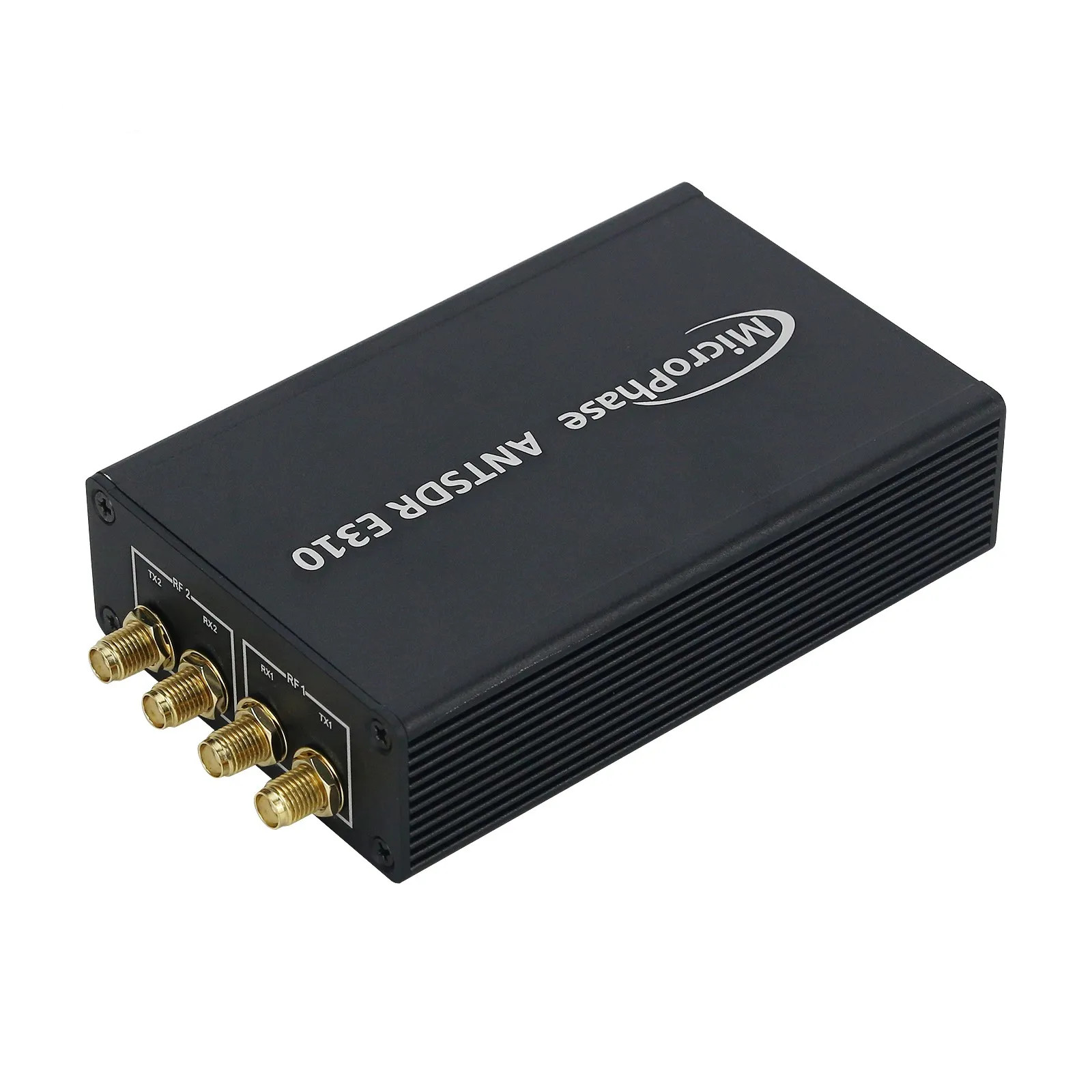
These inputs are wired to an AD9363, which is rated for a frequency range between 325 MHz and 3.8 GHz. While this looks like a problem (our frequency of interest is in 143.050 MHz), Alexandru Csete found out these limits are purely nominal, and the PlutoSDR/AntSDR can be tricked into thinking that it has an AD9361 (which has a range of operation between 70 MHz and 6 GHz).
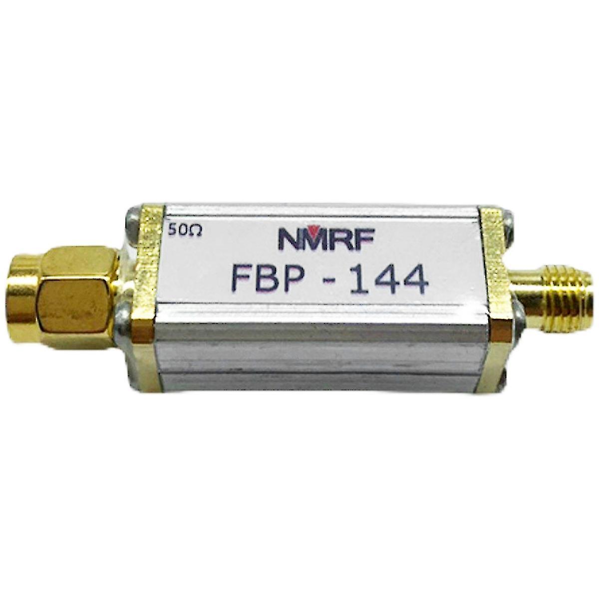
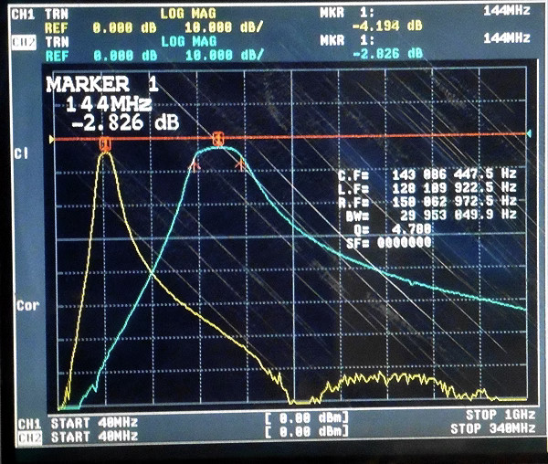
In theory, the AD9363 can work within the frequency limits of the AD9361 with degraded performance. In practice, the impact of this degradation (especially at the lower end of the limit) does not seem to be so severe. Nonetheless, both the PlutoSDR and the AntSDR are particularly sensitive to strong out-of-band signals (including GSM and FM broadcasts), and a couple of identical 2-m band-pass filters were necessary.
As usual, this is where things started to become unexplainably complicated. When I first bought the AntSDR, none of the available firmwares (neither the PlutoSDR nor the official ones for the AntSDR) supported 2r2t mode (i.e. coherent operation). The OpenWifi project provided firmwares and examples for dual antenna reception, but none of them seemed to be easily extendable to more general use cases.
Some time had to pass until I asked around in Twitter about 2r2t mode again, and this time I got a response by this guy who provided me with a working example I could reproduce in my computer. It was not easy, though: in the time between I bought my AntSDR and actually wanted to use it, a newer version of the E310 was released, and the newest firmware did not work in the oldest versions out of the box. Fortunately, older versions of the firmware were available in GitHub, and the instructions to enable 2r2t mode in the latest firmwares also worked for the oldest ones.
Lone-boy’s working example was the starting shot for writing my own direction finding plugin for SigDigger (GitHub of the AntSDRPlugin here). Once again, things did not go as smooth as I’d love to.
To be continued in Part II